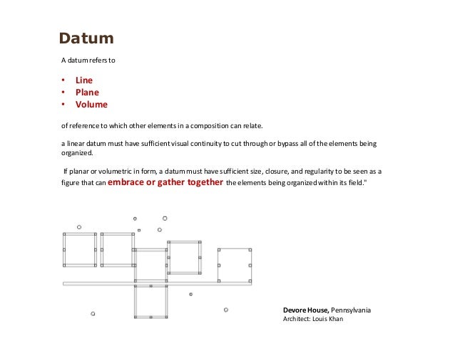


If there is not sufficient space within the compartment, the information may be placed outside and connected to the appropriate compartment by a leader line”. The upper compartment is reserved for additional information, such as dimensions of the target area. The letter represents the datum feature and the digit the datum target number. The lower compartment is reserved for a letter and a digit. ĭatum Target Frame: “The datum targets are indicated by a circular frame divided in two compartments by a horizontal line. ĭatum Reference Frame: A framework that consists of three mutually perpendicular datum planes, three datum axes (located at the intersection of each pair of datum planes), and a datum point (that is located at the intersection of the three datum planes).ĭatum Target: “A specified point, line, or area on a part used to establish a datum”. ĭatum System: “A group of two or more separate datums used as a combined reference for a toleranced feature”. ĭatum Feature Symbol: “The symbolic means of indicating a datum feature consists of a capital letter enclosed in a square frame and a leader line extending from the frame to the concerned feature, terminating with a triangle”. ĭatum Feature: “An actual feature of a part that is used to establish a datum”. A datum is the origin from which the location or geometric characteristics of features of a part are established”. These definitions are important, because they explain some of the concepts that are at the foundation of these GD&T standards, and consequently form the basis for the requirements of the DSCDM.ĭatum: “A theoretically exact point, axis, or plane derived from the true geometric counterpart of a specified datum feature. Most of the following definitions are from existing drawing-based GD&T standards and associated reference books. Geometric Dimensioning and Tolerancing Definitions These diagrams and examples not only aid in explaining the DSCDM, but also provide a set of test cases by which the validity of both the DSCDM and the Part 47 model may be judged.ģ. Furthermore, most of the diagrams and examples presented in this paper are from these same sources. 3 of this paper, which define the concepts that form the basis for the requirements of the DSCDM, are from these standards and associated reference books. Consequently, most of the definitions in Sec. Consequently, these drawing-based standards define the main requirements of the GD&T model and subsequently of the DSCDM. With the increased geometric complexity of printed circuit boards, printed circuit assemblies, and electronic components, it was deemed by members of the STEP AP 210 development team that the concepts presented in these GD&T drawing-based standards that are typically considered applicable to mechanical products are also applicable to the electronic products to which STEP AP 210 pertains. The reason that these existing GD&T standards are used to define the requirements of the DSCDM is due in part to the fact that the DSCDM is based on parts of a larger GD&T model that the author developed for STEP AP 210, Electronic assembly, interconnect and packaging design.
#Datum line definition iso#
In regard to the DSCDM, the requirements came from existing GD&T drawing-based standards (e.g., ASME Y14.5M, ISO 1101, and ISO 5459 ). “The first step in data modeling is to define the data requirements”. The model presented in STEP Part 47 will be referred to as “the Part 47 model” throughout the remainder of this paper. Additionally, a portion of the data model presented in STEP Part 47 is reviewed and a comparison is made between it and the DSCDM. This paper presents this data model, which will be referred to throughout the remainder of the paper as the DSCDM (Datum System Conceptual Data Model). The portion of the semantics that this data model defines encompasses the concepts of datum systems, datums, datum features, and datum targets. As “a data model is an effective technique to define the shareable semantics that are essential to the success of data communication in an integrated environment”, a conceptual data model has been developed that defines a portion of the semantics necessary for the electronic exchange of GD&T data among the design, manufacturing, and inspection divisions of an enterprise. However, with the advent of computer-aided design, manufacturing, and inspection equipment, the ability to exchange these requirements in a computer-sensible manner has become increasingly more desirable. Traditionally, geometric dimensioning and tolerancing (GD&T) requirements have been exchanged with technical drawings.


 0 kommentar(er)
